
- Product Catagory
- Tensile Strength Testing Machine
- Cables Flammability Testing Equipment
- Building Materials Flammability Testing Equipment
- Luggage Test Machine
- Textile Testing Equipment
- Color Fastness Instruments
- Textile Physical Test Instruments
- Lab Dyeing Instruments
- Flammability Test Chamber for Textile
- Consumables for Textile Testing
- Toys Safety Testing Equipment
- Physical & Mechanical Testing
- Flammability Testing
- Clamps for Toy Testing
- EN71-8,ISO8124-4
- Furniture Testing Machine
- Chair Testing Machine
- Mattress Testing Machine
- Furniture Testing Equipment
- Tables Test Machines
- Enviromental Chamber
- Leather and Footwear Testing Instruments
- Mobile Phone Testing Equipment
- Contact us
- Tel:86-769-23830463,86-13751491529
- Fax:86-769-38818154
- Contact:Ivy Xie
 [email protected]
 - Msn
 [email protected]
- Whatsapp/Wechat +8613751491529
- Skype
 skylineinstruments
- happy_go_lucky4477
- Site:Home > Cables Flammability Testing Equipment > SL-UL1666 Cable Installed Vertically in Shafts Fire Testing Machine
- Product Images
- detailed description
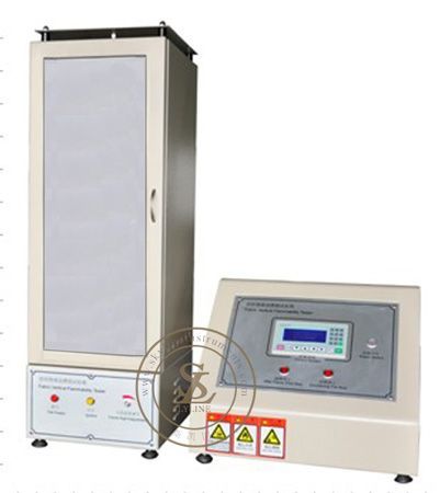
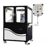
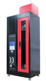
UL 1666 Cable Installed Vertically in Shafts Fire Testing Machine
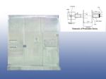
Testing StandardsUL1666, ANSI/ASTM D 5207 & UL 1581, ANSI/ASTM D 5025UL1666<<Test for flame propagation height of electrical and optical-fiber cables installed vertically in shafts>>Technical Parameters1. U-type pressure gauge: measuring chamber pressure maintained at 0-12PA;2. Hygrometer: measuring chamber temperature and humidity;3. The structure of the chamber: the overall structure of the concrete wall by the brick, the first layer is 1.22M, the second layer is 3.66M, the top is 2.24M. External dimensions: 7.12M high x1.3M wide x2.5M long;4. The wall structure is a density of 106lb / ft3 (1698kd / m3) of concrete, the thermal conductivity (k) at 21.1 ℃ for the 0.38Btu (0.055W / mk);5. The first and second layer by the 203mm thick ordinary weight of the cement composition.Roof is made of wall to ensure its tightness;6. The measuring hole in the second layer must be above the vertical hole of the first layer measuring hole (305mm by 610mm), each hole is 203mm behind the box and 102mm from the side of the box.
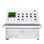
Ignition device1. A 1/2 inch steel pipe, a 1/2 inch pipe elbow and a steel ignition dispersing disc are installed, and a propane flow meter is installed at the place where the gas is injected.2. Fan: Install the exhaust fan and anemometer at the outlet of the test box.3. Combustion source: The gas supplied to the igniter must be CP grade propane and the heat per cubic foot is 2500 Btu.4. Exhaust fan and conveying pipe: The steel conveying pipe is installed at the center of the top of the test box. The exhaust fan is connected to the conveying pipe.6. Temperature and flow test instruments: Eight special 28-type nickel sheath thermocouples are placed in the second tank, one thermocouple is placed in the first tank, and a special type 28 nickel sheath thermocouple is placed on the first floor. The center of the ceiling extends 1 ± 1 / 16 (25.4 ± 1.6 mm) perpendicular to the ceiling and the thermocouple is tested before the test chamber temperature is determined.7. The two-way wind speed probe is placed at the horizontal and vertical center of the first slot, and the speed measuring probe is connected to an electronic pressure gauge to obtain the differential pressure.8. Data acquisition instrument: PLC and computer are used. The digital data acquisition system collects and records the air velocity at the entrance hole and the temperature of the thermocouple of the second layer hole every 5 seconds and displays the curve.
- Related ProductsMore>>